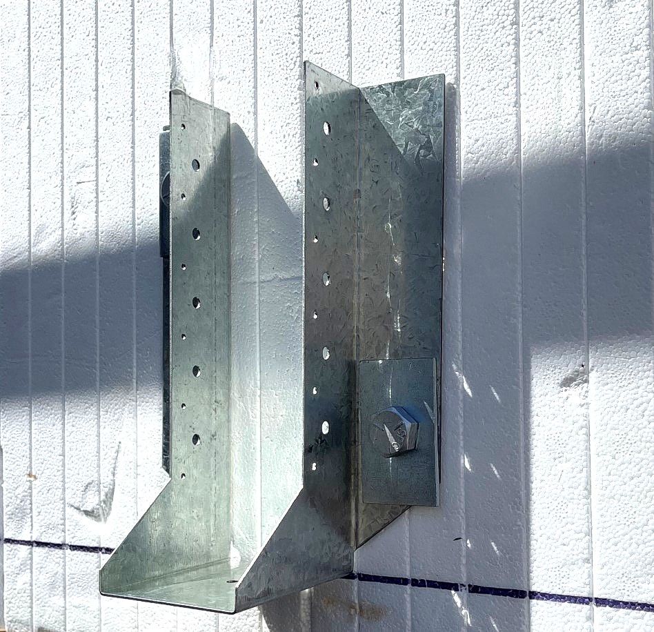
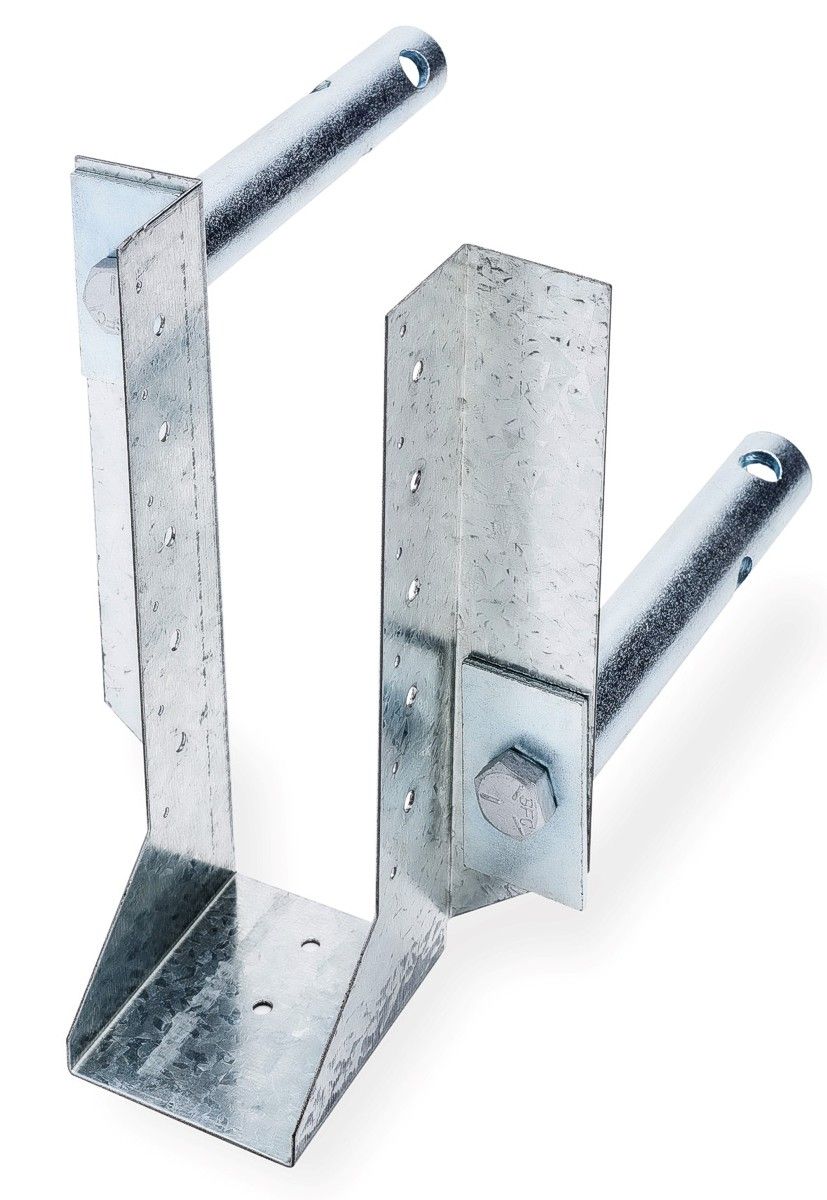
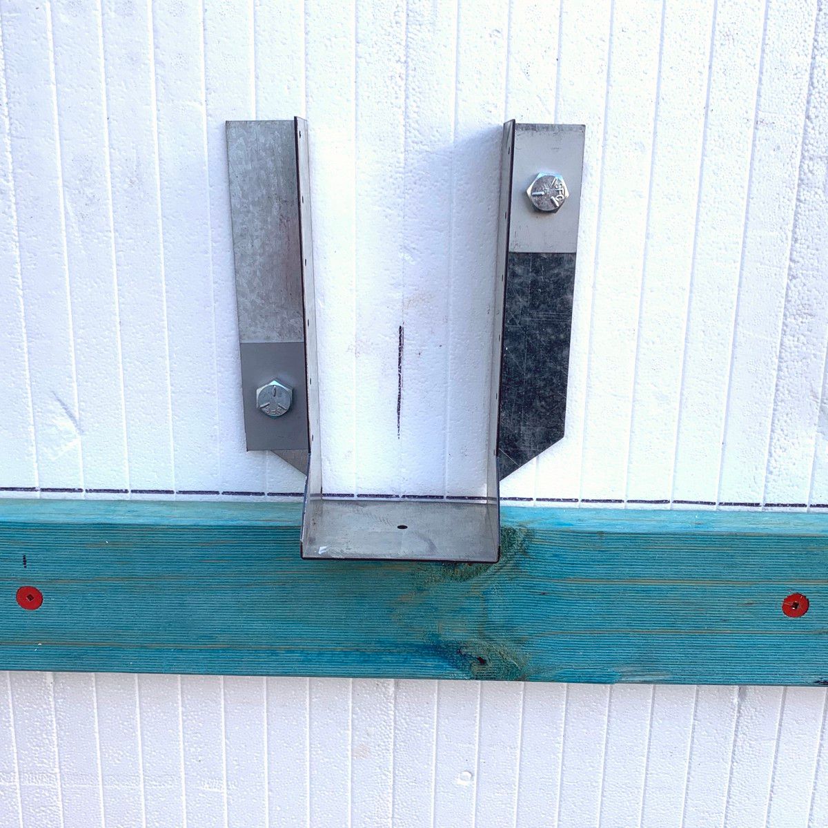
Burmon’s ICF Joist Hanger utilizes the Burmon ICF Connector System, a revolutionary double threaded cylinder bolt assembly that connects and anchors wood ledger brackets, wood and steel ledgers, joist hangers, I- joists, beams and trusses to insulated concrete forms (ICF) walls.
Burmon ICF Connector System
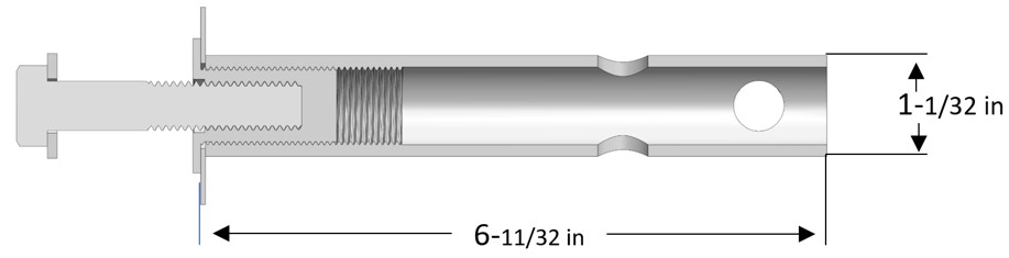
The cylinder bolt assembly is engineered with high capacity sheer points, which more efficiently absorbs the energy of the unsupported load transfer span, between the polystyrene inner and outer ICF wall. The embedded legs of the cylinder tube have openings to receive concrete and rebar (optional) and the high capacity bolts connect directly to the concrete within the ICF wall, enhancing strength, stiffness of connection, function and durability. US Patent Application 17/120,457.
Concrete should have a minimum compressive rate of f'c = 2,500 psi (17.25 MPa)
The bolts of BURMON-ICFJH must be no closer than 4 inches to the top of wall.
* If requiring pullout loads, place one ½ inch hex bolt 3½ inches long into each cylinder bolt hole.
NOTE:
The Allowable Load Table is calculated in accordance with ASTM D7147-11 Section 13, the allowable downward load is calculated as the lesser of:
The lowest ultimate load per hanger divided by 3.
The average, over each hanger in each specimen, load that produces a vertical deflection of 0.125 inches at the bottom of the hanger with respect to the wall. Refer to Intertek Engineering report K9541.01-119-42 RO for Test results.
Technical Info & Downloads
Note: DWG, EASM, STEP and EPRT 3d Models may be viewed using free EDrawings Viewer software