Join the Burmon Revolution
FBC Code Approvals Click here
Load Table
Allowable Loads (lb) - ASD | ||||
Vertical | Lateral | Pullout* | Uplift | Corrosion Finish |
2520 | 2490 | 2845 | 2330 | Galvanizing G90 |
* 5. ½ inch diameter, 3½ inch long Hex bolt
- Fasteners for wood ledgers provided with part
- Loads apply to ICF foam thickness of 3¼ or less.
- Concrete should have a minimum compressive rate of f'c = 2,500 psi (17.25 MPa)
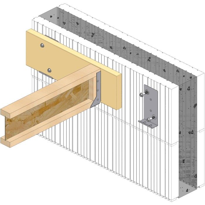
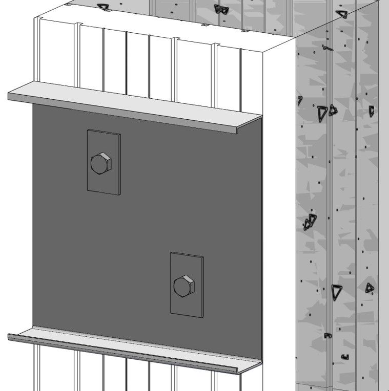
- The bolts of BURMON-ICFWL must be no closer than 4 inches to the top of wall.
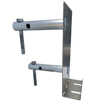
- * When attaching a deck to an ICF wall, place one ½ inch hex bolt 3½ inches long into each cylinder bolt hole as shown.
NOTE:
The Allowable Load Table is calculated in accordance with ASTM D7147-11 Section 13, the allowable downward load is calculated as the lesser of:
- The lowest ultimate load per hanger divided by 3.
- The average, over each hanger in each specimen, load that produces a vertical deflection of 0.125 inches at the bottom of the hanger with respect to the wall. Refer to Intertek Engineering report K9541.01-119-42 RO for Test results.
This table addresses vertical and pullout* load applications for foam thickness up to 3¼ inches. For foam thickness greater than 3¼ inches, contact our office for specific details.
Burmon ICFWL – Wood Ledger Spacing to Replace Anchor Bolts (inches) | |||||||||||||||||
Ledger Type | Model No. | ½ inch Diameter Anchors at | ⅝ inch Diameter Anchors at | (2) ⅝ inch Diameter Anchors at | ¾ inch Diameter Anchors at | ||||||||||||
12in O.C. | 24in O.C. | 36in O.C. | 48in O.C. | 12in O.C. | 24in O.C. | 36in O.C. | 48in O.C. | 12in O.C. | 24in O.C. | 36in O.C. | 48in O.C. | 12in O.C. | 24in O.C. | 36in O.C. | 48in O.C. | ||
WOOD LEDGERS | |||||||||||||||||
2 x D.Fir-L/S-P-F | Burmon ICFWL | 48in | 48in | 48in | 48in | 38in | 48in | 48in | 48in | 19in | 38in | 48in | 48in | 34in | 48in | 48in | 48in |
1¾ SCL | Burmon ICFWL | 48in | 48in | 48in | 48in | 34in | 48in | 48in | 48in | 17in | 34in | 48in | 48in | 28in | 48in | 48in | 48in |
STEEL LEDGERS | |||||||||||||||||
16 gauge (0.060 inches) | Burmon ICFSL | 20in | 40in | 48in | 48in | 16in | 32in | 48in | 48in | ||||||||
14 gauge (0.075 inches) | Burmon ICFSL | 16in | 32in | 48in | 48in | 13in | 26in | 39in | 48in | ||||||||
- The Designer may specify different spacing based on load requirements. It is recommended to space the components at multiples of the joist spacing to help reduce the chance of interference with the joist hangers.
- Spacings are based upon the perpendicular to grain capacity of a bolt in a wood ledger compared to tested value of ICFWL.
ICFSL Load Table
Allowable Loads (lb) - ASD | |
Vertical | Lateral |
2150 | 2050 |
- Fasteners for steel ledgers provided with part
- Minimum steel ledger thickness is 16 gauge, 54mm steel ledger
- Loads apply to ICF foam thickness of 3¼ or less.
- Concrete should have a minimum compressive rate of f'c = 2,500 psi (17.25 MPa)
- The bolts of BURMON-ICFSL must be no closer than 4 inches to the top of wall.
NOTE:
The Allowable Load Table is calculated in accordance with ASTM D7147-11 Section 13, the allowable downward load is calculated as the lesser of:
- The lowest ultimate load per hanger divided by 3.
- The average, over each hanger in each specimen, load that produces a vertical deflection of 0.125 inches at the bottom of the hanger with respect to the wall. Refer to Intertek Engineering report K9541.01-119-42 RO for Test results.
The following spacing tables are an alternative to the ICFWL spacing to replace anchor bolts tables or allowable loads. They give the spacing of the ICFWL Ledger Connectors based on the allowable vertical load of the connector, the load on the floor and the span of the joists. The Designer must determine the design load, the ledger design and the joist design. This table is useful if the Designer already has loads and spans, but not necessarily anchor bolt spacing.
* Values in the cells highlighted represent the maximum allowable spacing of 48".
Spacing for Burmon ICFWL (in.) | |||||||||||
Uniform Loads | Joist Span (ft.) | ||||||||||
Dead Load (psf) | Live Loads (psf) | 10 | 12 | 14 | 16 | 18 | 20 | 22 | 24 | 26 | 28 |
10 | 40 | 48 | 48 | 48 | 48 | 48 | 47 | 42 | 39 | 36 | 33 |
15 | 40 | 48 | 48 | 48 | 48 | 47 | 42 | 38 | 35 | 33 | 30 |
20 | 40 | 48 | 48 | 48 | 48 | 43 | 39 | 35 | 32 | 30 | 28 |
10 | 60 | 48 | 48 | 48 | 42 | 37 | 33 | 30 | 28 | 26 | 24 |
20 | 60 | 48 | 48 | 42 | 36 | 32 | 29 | 26 | 24 | 22 | 21 |
30 | 60 | 48 | 43 | 37 | 32 | 29 | 26 | 24 | 22 | 20 | 18 |
40 | 60 | 47 | 39 | 33 | 29 | 26 | 23 | 21 | 19 | 18 | 17 |
10 | 100 | 42 | 35 | 30 | 26 | 24 | 21 | 19 | 18 | 16 | 15 |
20 | 100 | 39 | 32 | 28 | 24 | 22 | 19 | 18 | 16 | 15 | 14 |
Spacing for Burmon ICFSL (in.) | ||||||||||
Uniform Loads | Joist Span (ft.) | |||||||||
Dead Load (psf) | Live Loads (psf) | 10 | 12 | 14 | 16 | 18 | 20 | 22 | 24 | 26 |
10 | 40 | 36 | 36 | 36 | 36 | 36 | 35 | 31 | 29 | 27 |
15 | 40 | 36 | 36 | 36 | 36 | 35 | 31 | 28 | 26 | 24 |
20 | 40 | 36 | 36 | 36 | 36 | 32 | 29 | 26 | 24 | 22 |
10 | 60 | 36 | 36 | 36 | 31 | 27 | 24 | 22 | 21 | 19 |
20 | 60 | 36 | 36 | 31 | 27 | 24 | 21 | 19 | 18 | 16 |
30 | 60 | 36 | 32 | 27 | 24 | 21 | 19 | 18 | 16 | 15 |
- Spacing tables address vertical load applications only. If the connection is designed to resist simultaneous lateral loads, spacing may decrease. Contact Burmon Building Products for additional information.
- Values shown are maximum spacing distances (in.) based on simple span, uniformly loaded conditions and do not consider concentrated loads.
- Joist and ledger are to be designed by others.
- Allowable loads are based on testing, with no further increases allowed.
Technical Info & Downloads
Note: DWG, EASM, STEP and EPRT 3d Models may be viewed using free EDrawings Viewer software