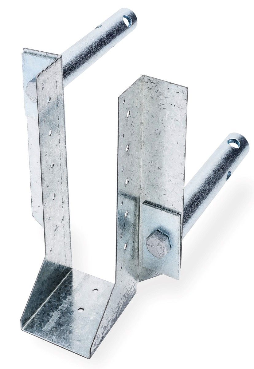
ICF Joist Hanger
Product code: ICFJH
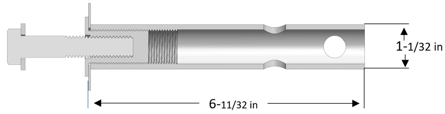
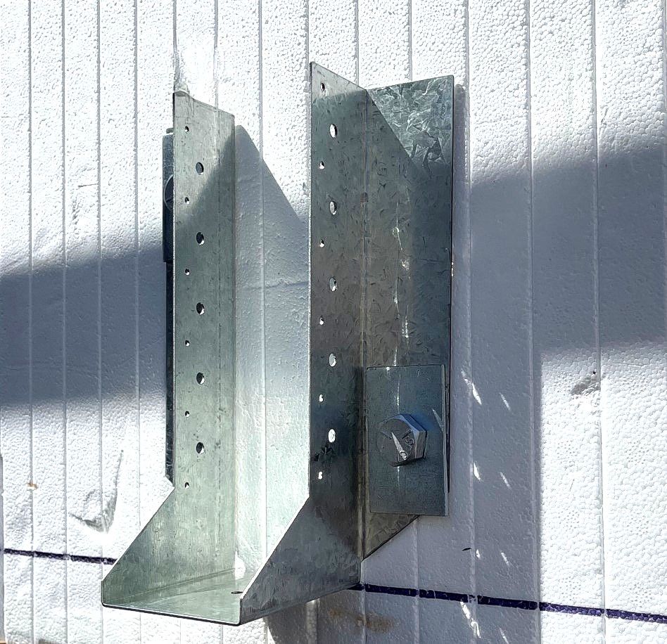
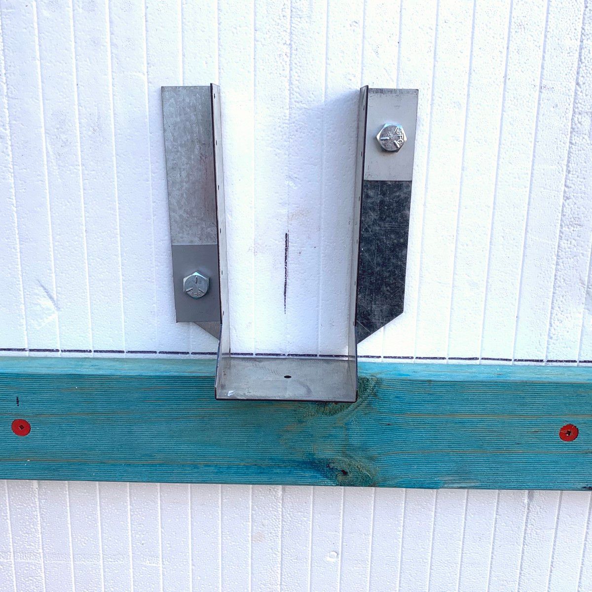
Burmon’s ICF Joist Hanger utilizes the Burmon ICF Connector System, a revolutionary double threaded cylinder bolt assembly that connects and anchors wood ledger brackets, wood and steel ledgers, joist hangers, I- joists, beams and trusses to insulated concrete forms (ICF) walls.