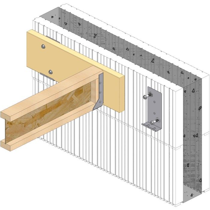
Burmon’s ICF Wood & Steel Ledgers utilize the Burmon ICF Connector System, a revolutionary double threaded cylinder bolt assembly that connects and anchors wood ledger brackets, wood and steel ledgers, joist hangers, I- joists, beams and trusses to insulated concrete forms (ICF) walls.
Burmon ICF Connector System
The cylinder bolt assembly is engineered with high capacity sheer points, which more efficiently absorbs the energy of the unsupported load transfer span, between the polystyrene inner and outer ICF wall. The embedded legs of the cylinder tube have openings to receive concrete and rebar (optional) and the high capacity bolts connect directly to the concrete within the ICF wall, enhancing strength, stiffness of connection, function and durability.
Features:
Fast & Easy to Install
Costs Significantly Less Than Ordinary Ledger Connectors
Revolutionary Double Cylinder Bolt Technology
Ledger Bracket, Bolts & Washers Supplied
Template Supplied for Marking Out Bolts
No Drilling Through Steel Plates
ICFWL designed for 1½ & 1¾ Wood Ledgers
25% Higher Capacity than other brand Ledger Connectors
Galvanizing G90 plus ceramic-coated bolts and washers salt tested 1000 hours for outside use
14.6 k/N
14.7 k/N
15.6 k/N
16.4 k/N
* 5. ½ inch diameter, 3½ inch long Hex bolt
Fasteners for wood ledgers provided with part
Loads apply to ICF foam thickness of 3¼ or less.
Concrete should have a minimum compressive rate of f'c = 2,500 psi (17.25 MPa)
The bolts of BURMON-ICFWL must be no closer than 4 inches to the top of wall.
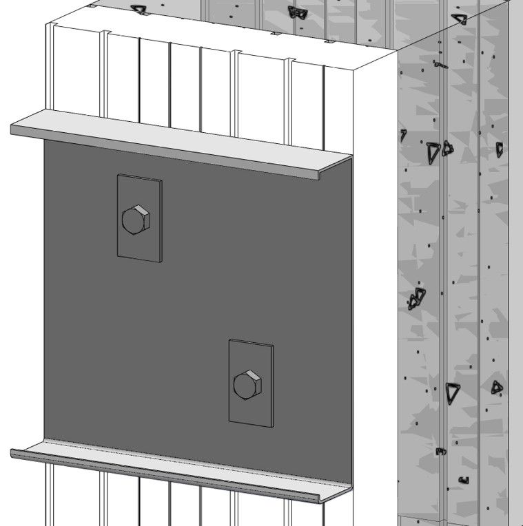
* When attaching a deck to an ICF wall, place one ½ inch hex bolt 3½ inches long into each cylinder bolt hole as shown.
This table addresses vertical and pullout* load applications for foam thickness up to 3¼ inches. For foam thickness greater than 3¼ inches, contact our office for specific details.
Minimum steel ledger thickness is 16 gauge, 54mm steel ledger
Loads apply to ICF foam thickness of 3¼ or less.
Concrete should have a minimum compressive rate of f'c = 2,500 psi (17.25 MPa)
The bolts of BURMON-ICFSL must be no closer than 4 inches to the top of wall.
The following spacing tables are an alternative to the ICFWL spacing to replace the building code-prescribed anchor bolt spacing for vertical loads only. They provide the recommended spacing of the ICFWL Ledger Connectors based on the Factored Vertical Resistance of the connector, the load on the floor and the span of the joist. The Designer must determine the design load, the ledger design and the joist design. This table is useful if the Designer already has loads and spans, but not necessarily anchor bolt spacing.
Spacing for Burmon ICFWL (in.)
* Values in the cells highlighted represent the maximum allowable spacing of 48".
Specified Load (psf)
Joist Span (ft.)
Live
Dead
10
12
14
16
18
20
22
24
26
28
30
32
40
10
48
48
48
46
41
37
33
31
28
26
24
23
15
48
48
48
42
38
34
31
28
26
24
22
21
20
48
48
45
39
35
31
28
26
24
22
21
19
25
48
48
42
37
32
29
26
24
22
21
19
18
30
48
46
39
34
30
27
25
23
21
19
18
17
50
10
48
48
44
38
34
30
28
25
23
22
20
19
20
48
45
38
33
30
27
24
22
20
19
18
16
30
48
40
34
30
26
24
21
20
18
17
16
15
40
43
36
30
27
24
21
19
18
16
15
14
13
100
10
33
27
23
20
18
16
15
13
12
—
—
—
20
30
25
22
19
17
15
14
12
—
—
—
—
30
28
24
20
18
16
14
13
12
—
—
—
—
40
27
22
19
16
15
13
12
—
—
—
—
—
Spacing for Burmon ICFSL (in.)
Uniform Loads
Joist Span (ft.)
Dead Load (psf)
Live Loads (psf)
10
12
14
16
18
20
22
24
26
10
40
36
36
36
36
36
35
31
29
27
15
40
36
36
36
36
35
31
28
26
24
20
40
36
36
36
36
32
29
26
24
22
10
60
36
36
36
31
27
24
22
21
19
20
60
36
36
31
27
24
21
19
18
16
30
60
36
32
27
24
21
19
18
16
15
Values shown are maximum spacing distances (inches) based on two-span ledger and simple supported joists. It does not consider concentrated loads. The Engineer of Record can modify the spacing accordingly for other conditions.
Joist and ledger are to be designed by others.
Spacing tables address vertical load applications only. If the connection is designed to resist simultaneous lateral loads, spacing may decrease. Contact Burmon Building Products for additional information.
The ICFWL must be installed no closer than 4" below the top of wall to achieve the connector spacing.
The maximum distance between the end of the ledger and the first ICFWL is 12" as per the recommended splicing installation.
Tables above assume Principal Loads only with Importance Factor = 1.00. For other cases adjust spacing accordingly.
Technical Info & Downloads
Note: DWG, EASM, STEP and EPRT 3d Models may be viewed using free EDrawings Viewer software